
![[field:title/]](/uploads/images/2023-04/6427b9f821135.jpg)
![[field:title/]](/uploads/hot/2205201701261816.jpg)
![[field:title/]](/uploads/hot/2211221654459051.jpg)
![[field:title/]](/uploads/hot/2112181335487845.jpg)


-
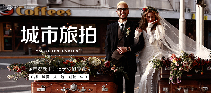
城市旅拍
寻觅一座城市,让记忆落地生根
-
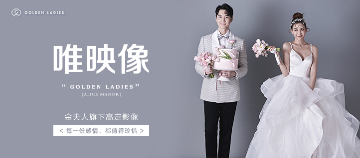
唯映像私属空间
尊享秀场高定,轻奢新韩体验
-
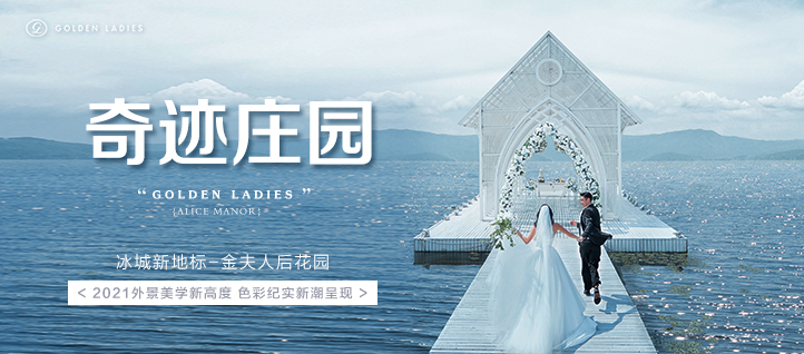
奇迹庄园
全新艺术美学空间,属于你的梦幻外景天堂
-

全球旅拍
拍遍全球浪漫美景,为你提供N种旅拍目的地


-
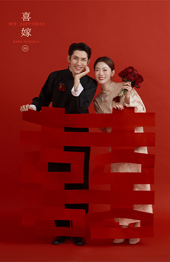
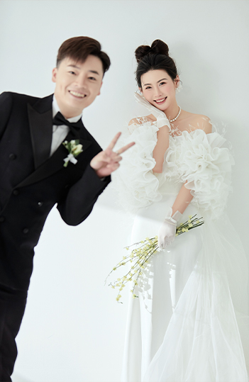
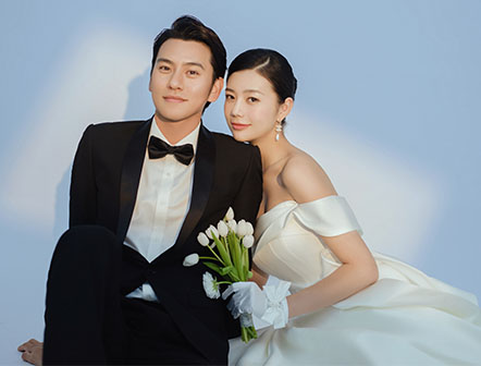
金夫人婚纱照客片
GoldenLadies
-
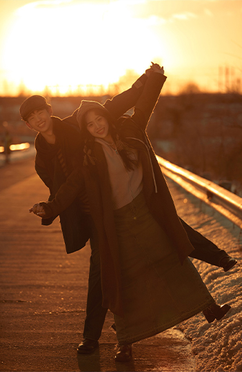
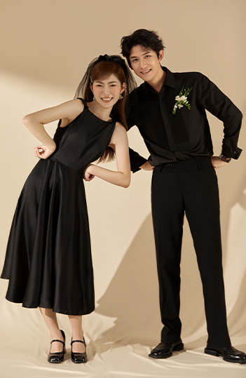
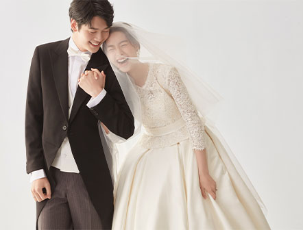
金夫人婚纱照客片
GoldenLadies
-
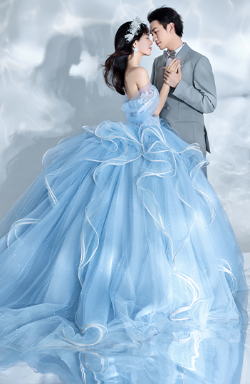
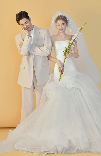
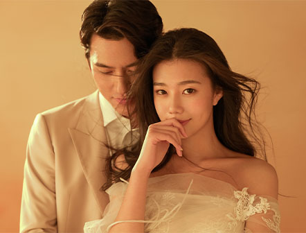
金夫人婚纱照客片
GoldenLadies
-
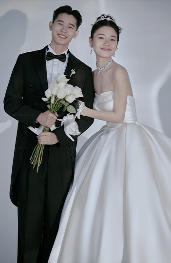
金夫人婚纱照客片
GoldenLadies
-
金夫人婚纱照客片
GoldenLadies
-
金夫人婚纱照客片
GoldenLadies
-
金夫人婚纱照客片
GoldenLadies
-
金夫人婚纱照客片
GoldenLadies


第一步
您的拍摄计划
第二步
喜欢的风格
第三步
拍摄场景
第四步
您的预算
第五步
输入手机号
输入手机号
立即提交

-
 胖新娘拍摄婚照显瘦攻略面对一生一次的婚纱照,每个女孩追求的都是完美无瑕,为了拍出完美的婚纱照,准新娘们都会想尽各种办法,让自己在婚纱照上的得到完美的展现。而对于身材微胖的准新娘来说,如... MORE
 -
 婚纱照为什么要提前预定?很多不了解影楼的顾客一直以来认为去婚纱店拍了照片,5、6天就能拿到自己宝贝的婚纱照,其实不是这样的哦。从预约拍照修调选片制作回件,整个流程下来没有两个月左右是不能取... MORE
 -
 哈尔滨婚纱照什么风格好看?众所周知,在哈尔滨拍婚纱照有多种多样的风格,在我们官网上面也可以看到,我们哈尔滨金夫人婚纱照风格有很多样,但是新人们都知道每种风格的特色吗?下面就随金夫人小编一起... MORE
 -
 每张婚纱照背后都有一个拼命的摄影师作为婚纱摄影行业的摄影师工作绝不容易,相信体验过的人都会理解到当中的辛酸。为了使 婚纱照 能拍出最好的角度,摄影师要做出各种高难度动作,甚至比较高危的动作,下面通过... MORE